Quick technical guide: This article explains industrial limit switch selection: the small component that tells a machine where it is for panel builders, contractors, maintenance teams and industrial electrical buyers.
A conveyor reaches the end of its permitted travel.
A machine slide arrives at its home position.
A valve mechanism completes its movement.
A guard closes.
Something in the control system needs to know that the mechanical movement has actually happened.
In many industrial machines, that job is handled by a limit switch.
A limit switch converts physical movement into an electrical signal. ABB describes limit switches as devices that convert mechanical movement into electrical signals through contacts mechanically linked to an actuator.
ABB Group
The principle is simple. Selection is not.
A replacement switch can have the correct number of contacts and still be wrong because its actuator, operating direction, mechanical travel, contact action, enclosure or electrical duty does not suit the machine.
For maintenance teams, the old switch's complete mechanical arrangement can matter just as much as the wiring diagram.
What happens inside a limit switch?
A mechanical limit switch normally combines three functional parts:
Actuator — the part physically contacted by the moving machine.
Operating mechanism — transfers that movement into the switch.
Electrical contacts — change state when the mechanism reaches its operating point.
The machine does not need to measure distance electronically. It only needs to move the actuator far enough for the contact mechanism to operate.
The control circuit then interprets the resulting contact state.
For example:
Machine travelling → switch not actuated
Machine reaches defined position → actuator moves → contact changes state
That contact can signal a PLC, operate a control relay, stop a contactor circuit or initiate the next step in a machine sequence.
The limit switch generally reports a physical position. It does not determine by itself what the machine should do next.
Why actuator selection matters
Look at an industrial limit-switch catalogue and the first obvious difference is often the head.
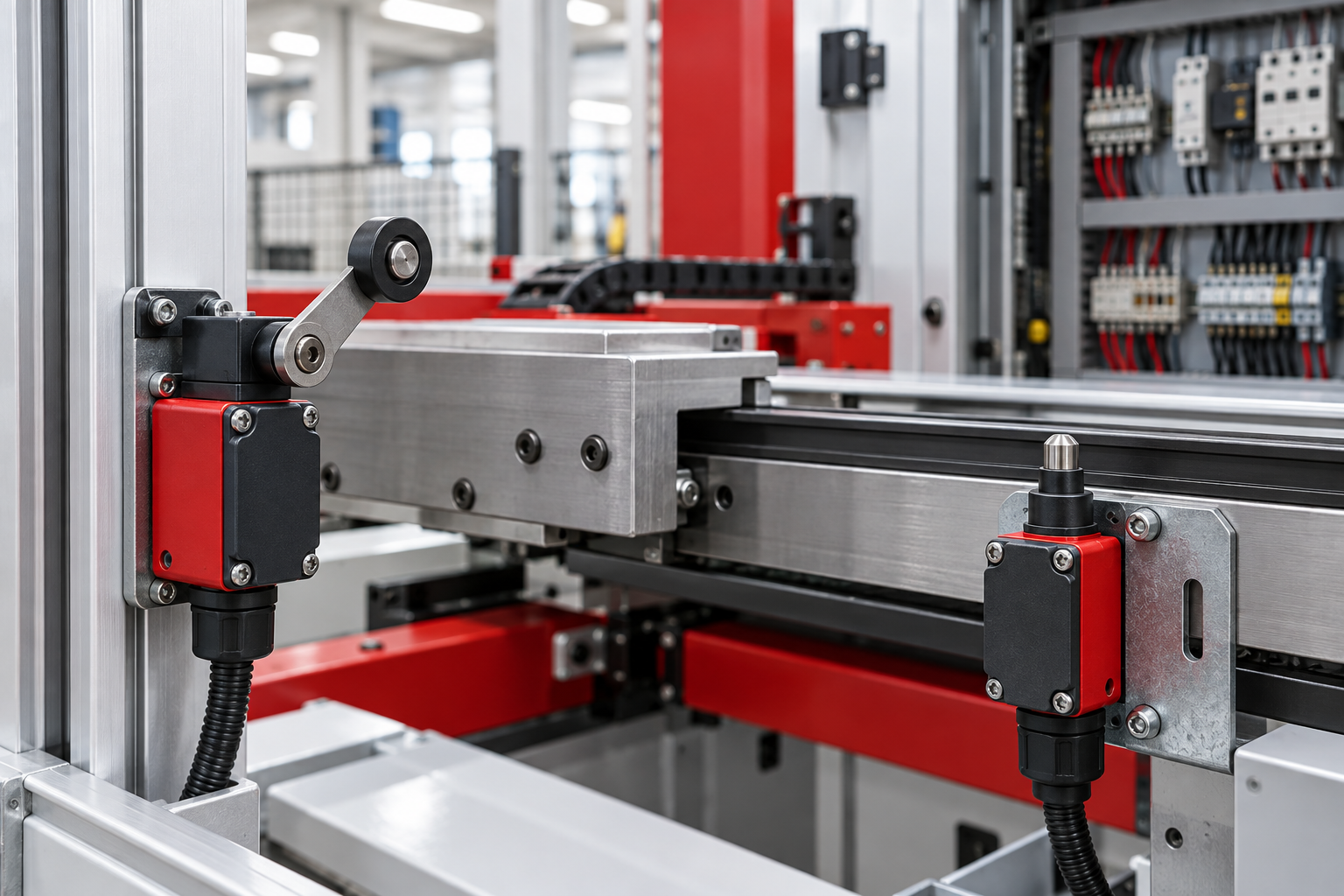
One switch may have a roller lever.
Another uses a plunger.
Another may use a flexible actuator intended to tolerate approach from different directions.
Those shapes are functional, not cosmetic.
The correct actuator depends on how the moving part approaches the switch, how much travel is available and whether sliding contact between the machine and actuator is expected.
ABB's current limit-switch range reflects this application-driven approach: different actuator and casing combinations are provided to suit different mechanical movements.
ABB Group
A switch body that fits the mounting holes is not enough.
When is a roller lever useful?
A roller lever is useful when a moving machine part approaches from the side and needs to move past the actuator rather than strike a fixed plunger head-on.
The roller reduces sliding friction at the contact point while the lever converts machine travel into rotational movement of the switch mechanism.
The exact approach direction matters.
Some adjustable-head switches can be configured for particular operating directions. Schneider Electric documents limit-switch heads that can be configured for clockwise, counter-clockwise or combined operation depending on the model.
Schneider Electric
Do not assume every roller lever operates identically in both directions.
When does a plunger make sense?
A plunger actuator is suited to applications where the moving component can approach the switch in a controlled direction and directly depress the actuator.
It can provide a compact arrangement for detecting a defined end position.
But mechanical alignment becomes important.
If a cam hits the plunger at an unsuitable angle, excessive side loading or overtravel can damage the switch or mounting.
The machine should operate the actuator in the manner defined by the manufacturer.
A limit switch should detect the end position.
It should not become the mechanical end stop unless the equipment is specifically designed that way.
Do not use the switch as a crash stop
This is one of the most practical installation mistakes.
Suppose a travelling carriage reaches the end of a rail.
The limit switch should operate before the carriage reaches its mechanical travel limit.
If the carriage repeatedly drives hard into the actuator and uses the switch body to absorb its kinetic energy, the switch is being asked to perform a mechanical function it was not selected to perform.
Provide appropriate mechanical stops separately where the machine requires them.
The limit switch should have enough operating travel to switch reliably without being crushed by the mechanism.
What are pre-travel and overtravel?
A limit switch does not necessarily change electrical state the instant its actuator begins moving.
The actuator first travels through a certain distance or angle before the contacts operate. That movement is commonly described as pre-travel.
After the operating point, some additional actuator movement may be permitted. That is overtravel.
There is also a reset or release point as the actuator returns.
These characteristics matter when replacing a switch on precision machinery.
Two switches can look almost identical while operating at different mechanical positions.
If a machine relies on a cam to trigger the switch at a specific point, changing the operating geometry can change the machine sequence.
Use the mechanical operating diagram for the exact switch when timing or travel is important.
Snap action vs slow action
The internal contacts do not all behave the same way.
A snap-action mechanism changes contact state rapidly once the actuator reaches its operating point. The contact movement is produced by the internal mechanism rather than simply following actuator speed throughout the entire switching movement.
ABB currently lists snap-action contact elements on industrial limit-switch models such as its LS35 series.
Empower
Other limit switches use slow-action or dependent-action contacts where contact movement follows actuator movement more directly.
The choice can affect switching behaviour and suitability for particular control functions.
Do not substitute one contact mechanism for another solely because both devices provide 1NO + 1NC terminals.
What does 1NO + 1NC mean?
It means the switch provides:
One normally open contact
One normally closed contact
"Normal" refers to the switch's unactuated state.
When the actuator operates, the NO contact changes toward closed while the NC contact changes toward open according to the switch mechanism.
ABB's current LS35P31B11, for example, is documented with one NO and one NC snap-action contact.
Empower
That is an ABB product example, not an INTEKS specification.
Other switches may provide different contact arrangements.
Always record the actual contact diagram before replacing a switch.
Why use the NC contact for a stop function?
An NC contact can provide a useful control characteristic in some stop or permissive circuits.
During normal healthy operation, the circuit passes through the closed contact.
When the limit switch is actuated, the contact opens and interrupts the control path.
This can also make certain wiring failures easier to detect than an arrangement that depends solely on closing a contact to generate a stop command.
However, an ordinary NC contact should not automatically be described as a safety contact.
Safety applications have additional requirements.
What is positive opening?
For certain limit switches, the NC contact can have positive-opening operation.
Schneider defines positive operation as a mechanical arrangement where the closed contact elements can be driven with certainty to the open position by the actuator, without relying on a flexible link in the opening mechanism.
Schneider Electric
That distinction can matter where a switch forms part of a safety-related control function.
A standard NC contact and a documented positive-opening contact are not automatically equivalent.
Look for the manufacturer's specific positive-opening information for the exact switch.
Can any limit switch be used as a safety switch?
No such assumption should be made.
Schneider notes that a conventional limit switch can only be considered for certain safety applications when requirements such as positive action are satisfied, and that other conditions—including redundancy and sensor integrity—may also be necessary.
Schneider Electric
Machine safety has to be assessed as a complete function.
A switch with an NC terminal does not, by itself, create a compliant guard interlock or emergency safety system.
Where personnel protection depends on position detection, use the machine's safety design and the documentation for the dedicated safety components involved.
Neutral-position limit switches solve a different problem
Some applications need to detect movement on either side of a centre position.
A conveyor belt tracking system is a good example.
Schneider describes a neutral-position limit switch where movement in one direction operates one contact set and movement in the opposite direction operates another. One documented application is detecting whether a conveyor belt has moved left or right of centre so that corrective action can be applied.
Schneider Electric
This is different from a normal roller-lever switch that merely happens to move in both directions.
The internal contact function needs to support the application.
Two-stage switches can detect more than one position
Some mechanical switches provide sequential contact operation.
Schneider's documentation for a two-stage limit switch describes two contact sets operating one after the other as the actuator moves from rest toward full travel. During return movement, the second stage resets before the first.
Schneider Electric
That can be useful where the machine needs one signal before reaching a final limit and another at a later point.
For example, a control system might use the first position to reduce speed and the second as the final travel limit.
Whether that architecture is appropriate depends on the machine design.
A standard single-stage switch cannot simply be wired to imitate mechanical two-stage detection.
A PLC command is not proof of machine position
Suppose a PLC energizes a motor contactor to move a mechanism forward.
The PLC knows that it issued the movement command.
It does not necessarily know that the mechanism actually reached the destination.
A limit switch can provide that physical confirmation.
This distinction becomes useful in sequence control:
PLC commands movement
Mechanism travels
Limit switch changes state
PLC receives position confirmation
Next sequence step begins
If the motor runs but the expected limit input never arrives, the controller can identify an incomplete movement instead of blindly advancing the sequence.
That is one reason mechanical position feedback remains useful even in highly automated machines.
What if the limit switch operates but the PLC input does not change?
Do not replace the switch immediately.
First establish where the signal is lost.
Check whether the actuator physically moves through the required travel. Then test whether the correct contact changes state using appropriate isolated procedures.
If the contact works, inspect the control wiring, terminals, supply to the input circuit and PLC input channel.
A mechanically damaged actuator and an electrical wiring fault can produce the same symptom on an HMI:
Limit not reached.
Troubleshooting should separate the mechanical and electrical sides.
What if the switch keeps breaking?
Repeated limit-switch failure usually deserves investigation beyond replacing the component.
Check whether:
The actuator is being struck too hard
Machine alignment has changed
Excessive overtravel is occurring
The switch has become the mechanical end stop
The mounting bracket is moving
Vibration is excessive for the installation
Water, oil or dust is entering the device
The actuator type is unsuitable
The electrical load is inappropriate for the contacts
A stronger-looking switch will not correct bad machine geometry.
Environment matters
Limit switches often live closer to the machine than the protected equipment inside the electrical panel.
That exposes them to dust, coolant, oil, vibration, moisture and physical impact.
The enclosure and cable entry therefore matter.
ABB's current industrial limit-switch portfolio includes plastic and metal housings with specified ingress-protection options for harsh environments.
ABB Group
Those ABB ratings should not be transferred to another manufacturer's switch.
For a replacement, match the required environmental protection from documented product data rather than assuming every enclosed limit switch is dust- or water-resistant.
Electrical contact rating still needs checking
A limit switch may only send a small PLC input signal.
In another machine, its contact might switch a relay or contactor coil.
Those are different electrical duties.
Contact ratings depend on voltage, current type and load characteristics.
ABB's current LS35 product data, for example, separately specifies its contact characteristics and pilot-duty information rather than giving one universal switching figure.
Empower
Do not select a replacement solely because its contacts are marked "10 A" or another headline current.
Check the rating for the actual control circuit.
Replacement requires more than matching the body size
Before removing an old switch, photograph it from several angles.
Record:
Complete model number
Actuator type
Actuator orientation
Operating direction
Contact arrangement
Contact action
Mounting-hole positions
Cable-entry arrangement
Required environmental protection
Control voltage and switched load
Mechanical approach direction
Existing cam or target position
Also mark the mounting position before loosening the switch.
A few millimetres of installation change can alter when the machine detects its limit.
Commission the mechanical position after replacement
After installing a replacement, do not immediately return the machine to unrestricted automatic operation.
Verify the switch manually or at appropriately controlled machine speed according to the site's commissioning procedure.
Confirm that the actuator reaches the operating point before the mechanism reaches its mechanical limit.
Check reset behaviour as the machine moves away.
Then verify the corresponding PLC input, relay or control action.
The replacement is not complete merely because the wires fit.
A better limit-switch purchasing request
Instead of:
"Need 1NO 1NC roller limit switch."
provide the information that determines compatibility.
State the existing switch model where available, actuator style, approach direction, contact arrangement, control voltage, switched load, mounting constraints and environmental conditions.
For machine replacement work, send clear photographs showing both the switch and the part of the mechanism that operates it.
That context can be more useful than a close-up of the label alone.
INTEKS supplies industrial electrical control, protection and automation components for panel builders, contractors, maintenance teams and industrial users. Limit switches should be selected around the machine movement, control function and installation environment rather than by contact count alone.
Frequently asked questions
What is the main purpose of an industrial limit switch?
A limit switch converts physical machine movement into an electrical contact signal. It can be used to confirm position, stop travel, initiate another control step or provide status to a PLC.
ABB Group
What is the difference between a roller-lever and plunger limit switch?
A roller lever is commonly suited to a moving cam or machine part passing across the actuator. A plunger is operated by direct linear movement. The correct choice depends on approach direction, travel and mechanical geometry.
What does snap action mean?
A snap-action mechanism changes the electrical contacts rapidly once the actuator reaches its operating point instead of making contact movement directly follow actuator speed throughout the switching action. Industrial limit-switch ranges include both contact-action types depending on the model.
Empower
Can I use a normal limit switch on a machine guard?
Do not assume so. Safety-related position detection can require positive-opening contacts, suitable architecture, redundancy and other measures. The complete safety function has to be designed and validated for the machine.
Schneider Electric
+1
Why does a new limit switch operate at the wrong machine position?
The replacement may have different actuator geometry, pre-travel, mounting position or operating characteristics. Compare the exact mechanical data and readjust the installation according to the machine and switch documentation.
Related INTEKS guides
- Thermal Overload Relay Trip Class: Why Class 10, 20 and 30 Are Not Interchangeable
- What Does the kA Rating on an MCB Mean?
- Browse all INTEKS technical insights
For project requirements, component identification or a panel enquiry, contact the INTEKS team with the relevant rating, application and existing product details.
For the applicable standard and current edition, consult the official IEC publication search.