Quick technical guide: This article explains control transformer sizing: why adding up coil ratings is not enough for panel builders, contractors, maintenance teams and industrial electrical buyers.
A panel has a 415 V incoming supply, but its contactor coils, relays and indication circuit operate at a lower control voltage.
A control transformer provides that separate voltage.
The basic requirement sounds easy: choose the correct primary voltage, choose the required secondary voltage, then add up the control loads.
That last step is where mistakes begin.
Contactors, solenoids and other electromagnetic devices can demand considerably more apparent power while operating than they need once their magnetic circuits have closed. A transformer that appears large enough from steady-state consumption alone may therefore suffer excessive secondary-voltage drop at the exact moment the contactor needs to pull in.
For industrial control panels, transformer sizing has to consider both steady load and starting inrush.
What is a control transformer?
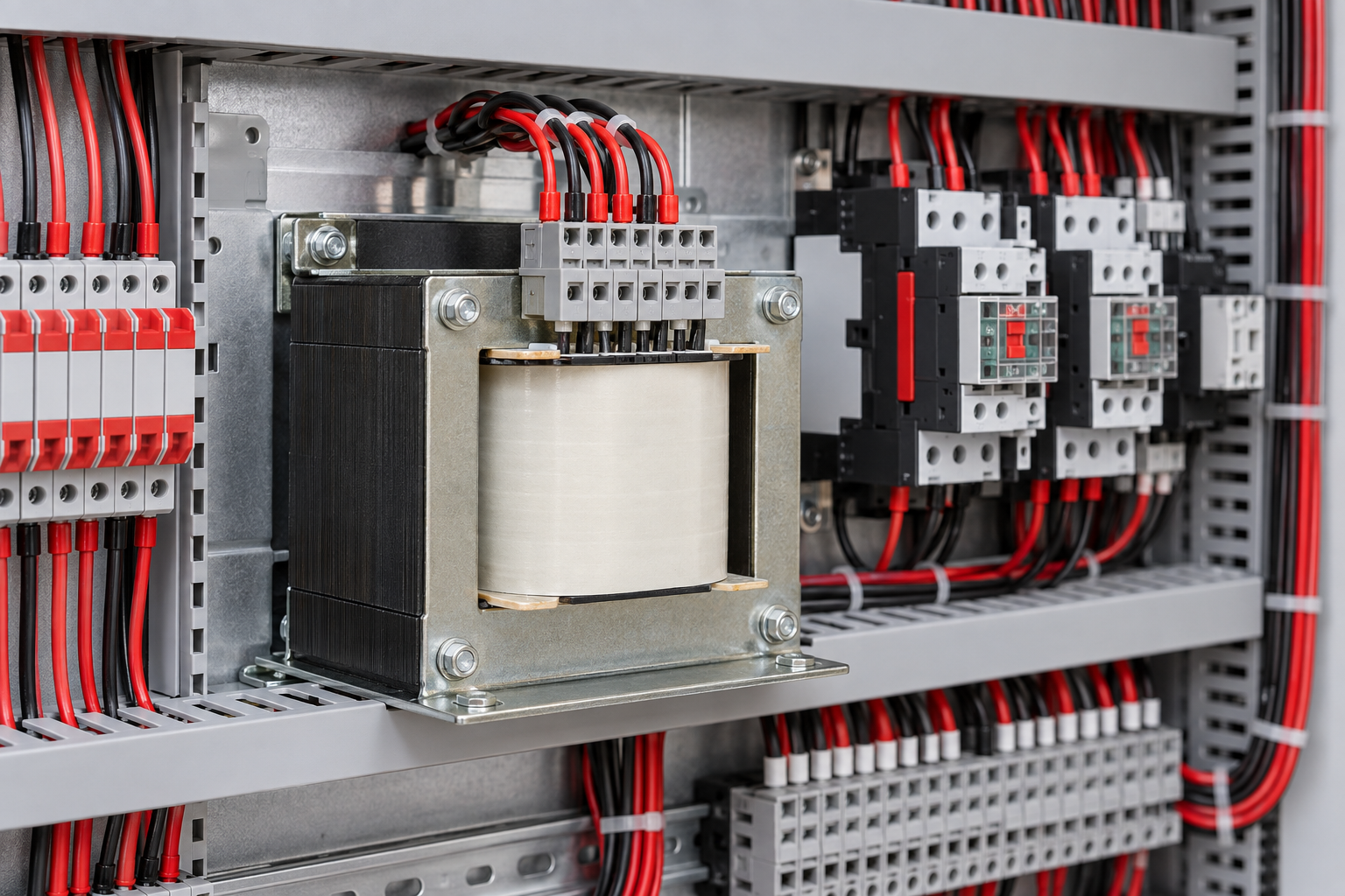
A control transformer changes the available supply voltage to the voltage required by an industrial control circuit.
Depending on the panel design, the secondary may supply devices such as:
Contactor coils
Control relays
Timers
Solenoid valves
Pilot devices
Other compatible control loads
ABB describes control-power transformers as suitable for applications including industrial control panels, HVAC equipment, signal and alarm systems and circuit isolation.
Empower
The actual primary and secondary voltages are product-specific. They must match the circuit design rather than being assumed from common local practices.
Primary voltage and secondary voltage come first
Before calculating VA, establish the voltage relationship.
If the available control-transformer supply is taken from a 400/415 V system and the control circuit requires another voltage, the transformer must have a winding arrangement explicitly suitable for those conditions.
Manufacturers may provide multiple primary taps or winding connections.
For example, current Schneider Electric Type T documentation shows transformers with alternative primary connections for 440, 460 and 480 V supplies and corresponding secondary voltage relationships.
Product Info
ABB likewise publishes specific control transformers with multiple primary voltage arrangements; one current model is documented for 380/400/416 V primary and 115/230 V secondary operation.
Empower
Those are manufacturer examples, not INTEKS specifications.
The important purchasing rule is simpler: never describe a control transformer only by VA. Include both required voltages.
What does VA mean on a control transformer?
Transformer capacity is normally stated in volt-amperes:
VA = Voltage × Current
For a simple example, a 24 V control load drawing 2 A represents:
24 × 2 = 48 VA
If that were the only steady load, 48 VA would describe its apparent-power requirement.
Industrial control circuits are rarely that simple.
Several devices may operate simultaneously, and electromagnetic devices can have one VA requirement while operating and another after they have settled.
That introduces two useful terms: sealed VA and inrush VA.
What is sealed VA?
Sealed VA is the apparent power required after an electromagnetic device has operated and reached its normal energized condition.
Siemens defines sealed VA, also called steady-state VA, as the voltage multiplied by current required by the control circuit after initial startup. For transformer selection, Siemens recommends adding the sealed VA of the components that can be energized at the same time.
Siemens Industry Cache
Consider a panel where these loads remain energized:
Main contactor coil
Auxiliary relay
Timer
Indication equipment
Their simultaneous steady-state requirements contribute to the transformer's sealed load.
But that calculation still does not tell us what happens when the contactor first closes.
What is inrush VA?
When a contactor or solenoid is initially energized, its magnetic circuit has not yet reached the closed position.
During that brief period, the device can demand substantially more current than it requires after closing.
That initial demand is represented by inrush VA.
Siemens defines inrush VA as voltage multiplied by the current required during circuit startup and states that the inrush requirements of devices energized together—including contactors, timers, relays, pilot devices and solenoids—need to be considered.
Siemens Industry Cache
The manufacturer's coil data is the correct place to obtain these figures.
Do not invent an inrush multiplier.
Different devices can have different operating characteristics.
Why a transformer can be large enough on paper but still cause contactor trouble
Imagine a transformer selected only from the steady-state consumption of the panel.
Everything appears correct after the machine is running.
Then a large contactor receives a start command.
Its coil draws its inrush current. The control transformer experiences the sudden VA demand, and its secondary voltage drops more than expected.
If the voltage at the coil becomes too low, the contactor may fail to close cleanly.
That can create symptoms such as:
Contactor chatter
Failed pickup
Repeated attempts to close
Unexpected control resets
Excessive heating at the electromagnetic device
Schneider Electric's transformer selection procedure explicitly checks the transformer's ability to maintain adequate secondary voltage during inrush rather than selecting from steady-state VA alone.
Product Info
This is why replacing a control transformer with another unit carrying the same secondary voltage but a smaller VA rating can cause a machine to behave differently.
Do all contactors start at the same time?
Usually not.
This matters.
Suppose a panel contains five contactors, but its control logic prevents more than one large contactor from pulling in at a time.
Adding the inrush VA of all five simultaneously could misrepresent the actual operating sequence.
Siemens' selection method specifically refers to devices that will be energized together when calculating inrush VA.
Siemens Industry Cache
Panel logic therefore belongs in the sizing calculation.
Ask what can actually happen during operation:
Can two motors receive a simultaneous start command?
Does one contactor have to close before another can energize?
Could the machine restart several loads together after a power interruption?
The schematic and sequence of operation can answer questions that the bill of materials cannot.
Existing sealed loads still matter during a new inrush event
Consider a machine that is already running.
Several relay and contactor coils remain energized. Then another contactor is commanded to close.
The transformer does not suddenly lose its existing load.
Its required performance during that event depends on the control devices already energized plus the inrush demand created by the newly operated device or devices.
This is why transformer selection tables use more than a simple total of nameplate values.
Schneider's current selection guidance compares total sealed VA and inrush requirements against transformer regulation characteristics to determine an appropriate VA rating.
Product Info
For an engineered panel, use the manufacturer's actual selection procedure for the transformer family being specified.
Why voltage regulation matters during inrush
A transformer's secondary voltage is not perfectly constant under every load condition.
As load increases, secondary voltage can fall.
The temporary high VA demand from electromagnetic control equipment can therefore cause a larger voltage drop than normal steady operation.
Schneider's Type T selection procedure evaluates available secondary voltage during inrush. Its current guidance recommends different selection columns depending on expected supply-voltage stability and specifically warns against relying on an excessively low secondary-voltage condition for repeated magnetic-device starting.
Product Info
That is more useful than simply buying "the next VA size up."
The transformer needs to support the actual control circuit during its most demanding operating event.
Bigger is not a substitute for calculation
Undersizing is an obvious concern, but blindly oversizing is not good specification practice either.
A larger transformer takes more panel space, changes protection requirements and increases cost and available secondary fault energy.
The better approach is to establish the real control load, determine the maximum simultaneous inrush condition, and then use the manufacturer's transformer-selection data.
A calculation also makes future maintenance easier because the designer can explain why a particular transformer size was chosen.
Primary and secondary protection need to be designed
A control transformer does not eliminate the need for appropriate circuit protection.
The primary circuit and, where required by the design, the secondary circuit need suitable protective arrangements.
Schneider's current industrial control transformer catalogue provides primary and secondary fuse-protection options across its transformer range, with the available arrangement depending on transformer VA and voltage.
Product Info
The exact fuse or breaker selection should come from the transformer manufacturer's instructions, applicable electrical design requirements and the available fault conditions.
Do not choose protection by copying the transformer's full-load current into the next convenient fuse size.
Transformer energization itself can involve inrush current, which must be considered by the protection design.
Check frequency as well as voltage
Voltage is not the only supply characteristic shown on transformer documentation.
Frequency matters too.
ABB's current control-transformer catalogue demonstrates this directly: specific products are published with defined 50 Hz or 60 Hz operating data, while other configurations may be suitable for both according to their documentation.
Empower
+1
When replacing an imported machine component, check the complete transformer nameplate.
A physically similar transformer with apparently correct voltages should not be substituted until its frequency and other ratings have been verified.
Multiple secondary voltages need careful wiring
Some control transformers provide multiple secondary winding connections.
That can allow different secondary voltages depending on how the terminals are connected.
Schneider's current Type T catalogue, for example, documents specific models with 24 V and 120 V secondary connection options.
Product Info
Never determine those connections by wire position or guesswork.
Use the terminal diagram for the exact transformer.
An incorrect series or parallel winding connection can apply the wrong voltage to the control equipment.
Troubleshooting a transformer that appears to have low secondary voltage
Do not replace it immediately.
Measure the primary voltage and secondary voltage using appropriate electrical procedures. Then determine whether the low secondary voltage occurs continuously or only when a particular contactor or solenoid operates.
If the voltage is normal with little load but collapses during a start command, investigate the connected load and transformer sizing.
Also inspect:
Loose terminals
Incorrect primary tap connection
Excessive secondary wiring voltage drop
Unexpected simultaneous loads
Damaged or failing coils
Added control equipment
Supply-voltage conditions
A panel may have operated correctly for years before somebody adds another contactor, relay or accessory to its control transformer.
The transformer did not necessarily deteriorate. The load may have changed.
Replacing an existing control transformer
Before disconnecting the old transformer, record the complete nameplate and terminal arrangement.
Useful information includes:
Primary voltage and taps
Secondary voltage and taps
Rated VA
Frequency
Number of phases
Existing primary protection
Existing secondary protection
Terminal identification
Physical dimensions and mounting
Control loads supplied by the transformer
If the original transformer failed, determine why before fitting the replacement.
A shorted control circuit or overloaded transformer can damage the new unit as well.
What panel builders should provide when requesting a transformer
A useful purchasing request contains more than:
"Need 500 VA control transformer."
Instead provide the primary supply voltage, required secondary voltage, frequency, total simultaneous sealed VA and the worst simultaneous inrush requirement.
Also provide the application, mounting constraints and protection requirements.
If the exact inrush data is unavailable, identify the contactors, solenoids and other magnetic devices so their manufacturer data can be checked rather than guessed.
INTEKS supplies industrial electrical protection and control components for panel builders, contractors, maintenance teams and industrial users. Control-power equipment should be specified from the actual circuit requirements rather than transformer VA alone.
Frequently asked questions
What is the difference between VA and watts on a control transformer?
VA represents apparent power and is calculated from voltage multiplied by current. Transformer and electromagnetic control-device selection commonly uses VA because AC loads can involve both real and reactive components.
Why is inrush VA higher than sealed VA?
An electromagnetic device such as a contactor can require substantially more current while its magnetic mechanism is moving into the closed position. Once closed, the current falls to its sealed or steady-state level.
Siemens Industry Cache
Can I size a control transformer by adding all the contactor coil VA ratings?
Not without considering operating sequence. Add the relevant simultaneous steady loads and determine which devices can produce inrush at the same time. The transformer's regulation during that event also needs to satisfy the manufacturer's selection requirements.
Product Info
+1
Why does a contactor chatter when another load starts?
One possible cause is control-voltage drop during inrush. Other possibilities include poor connections, incorrect coil voltage, supply problems or a defective contactor. Measure the control voltage during the event before assuming the transformer is undersized.
Can I replace a control transformer with a higher-VA unit?
A higher VA number alone does not establish compatibility. Primary and secondary voltages, frequency, protection, mounting, available fault conditions and the control-circuit design still need to be checked.
Related INTEKS guides
- MCCB Trip Units Explained: Thermal-Magnetic vs Electronic Protection
- Shunt Trip vs Undervoltage Release: Choosing the Right Circuit Breaker Accessory
- Browse all INTEKS technical insights
For project requirements, component identification or a panel enquiry, contact the INTEKS team with the relevant rating, application and existing product details.
For the applicable standard and current edition, consult the official IEC publication search.