Quick technical guide: This article explains thermal overload relays: what they protect and what electrical buyers should check for panel builders, contractors, maintenance teams and industrial electrical buyers.
A motor that draws too much current does not always fail immediately.
Sometimes the problem develops gradually. The motor is overloaded, one phase is lost, mechanical resistance increases, or operating conditions cause sustained current above the expected level. Heat builds inside the motor, and if the condition continues long enough, insulation and windings can be damaged.
This is where an overload relay becomes part of the motor starter.
For panel builders and maintenance teams, the important point is simple: a contactor switches the motor, while an overload relay helps protect it against sustained overload conditions. They are often installed together, but they perform different jobs.
What does a thermal overload relay do?
A thermal overload relay monitors the current flowing to a motor.
In a conventional thermal design, motor current passes through heating elements associated with bimetallic elements. When excessive current persists, the resulting heat causes the mechanism to operate. The relay then changes the state of its auxiliary contacts, which can interrupt the contactor control circuit and stop the motor.
ABB describes thermal overload relays as electromechanical motor-protection devices for overload and phase-failure conditions.
Empower
+1
The time element matters.
A motor can legitimately draw high current while starting. An overload relay therefore should not behave like an instantaneous short-circuit protective device every time starting current appears.
Its response is based on the magnitude and duration of the overload.
Overload protection is not the same as short-circuit protection
This distinction causes purchasing mistakes.
An overload relay is intended to protect against conditions such as sustained motor overload. It should not automatically be treated as the device providing short-circuit protection for the complete circuit.
Short circuits can produce extremely high currents and require suitable upstream protection, such as the correctly selected circuit breaker or fuse arrangement.
A typical motor starter may therefore involve several devices working together:
Circuit protection → Contactor → Overload relay → Motor
The exact arrangement depends on the application and the manufacturer's tested coordination data.
This also means that installing an overload relay does not remove the need to select the rest of the protection system correctly.
Why is the current adjustment important?
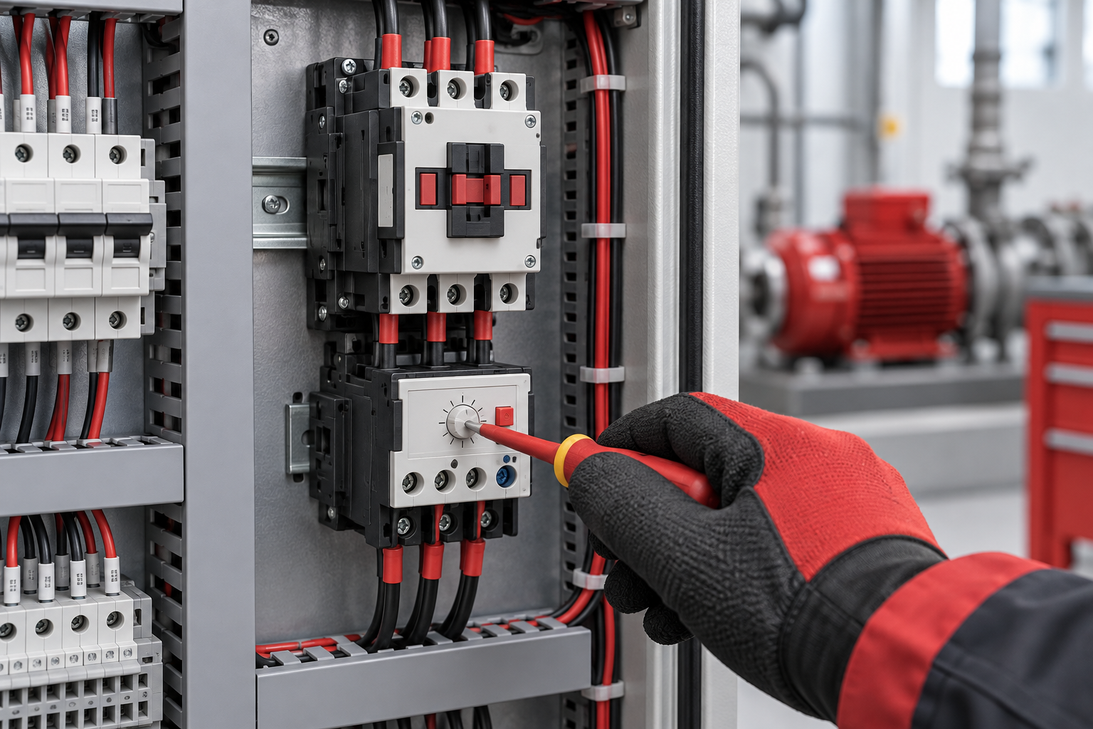
Many overload relays have an adjustable current range.
That range is there so the protection can be matched to the motor and application. It is not simply a knob for stopping nuisance trips.
Schneider Electric's guidance for its TeSys overload relays states that the current dial represents the motor nominal or full-load current, while the final setting must also respect the applicable installation rules and motor characteristics.
Schneider Electric
For a new installation, the motor nameplate is therefore one of the first places to look.
Suppose a motor nameplate shows a current that falls outside the adjustable range of the overload relay being considered. That should immediately trigger another selection check rather than an attempt to force the setting.
The manufacturer's selection documentation should be used for the specific relay and starter combination.
Why motor kW alone is not enough
Requests such as "I need an overload for a 7.5 kW motor" are common.
The motor power is useful information, but it does not fully define the required overload relay.
Motor voltage affects operating current. Motor design and application matter. The starter arrangement matters as well.
Schneider Electric lists factors including motor voltage, current, utilization category, number of phases and poles, overload current range and phase sensitivity when selecting contactors and overload relays.
Schneider Electric
For purchasing, a clear motor-nameplate photo is often more useful than sending only the kW value.
What is phase-loss sensitivity?
A three-phase motor normally depends on all three phases being available.
If one phase is lost while the motor is operating, current in the remaining phases can create damaging thermal conditions.
Overload relays designed with phase-loss sensitivity can respond to this situation. ABB's current overload-relay documentation specifically identifies overload and phase-failure protection as functions of its thermal overload devices.
ABB Group
+1
IEC 60947-4-1 also addresses phase-loss sensitivity for relevant overload protection devices. ABB's contactor and overload-relay guide explains that this characteristic is intended to cause tripping during a supply failure or severe phase imbalance before prolonged operation damages the motor or load.
ABB Library
That does not mean every overload relay on the market has identical phase-loss behaviour. Check the documentation for the actual device being specified.
What is trip class?
Two overload relays set to the same current do not necessarily trip in exactly the same way.
Trip class describes part of the relay's time-current behaviour under defined overload conditions.
Different motor applications can have different starting requirements. A motor that accelerates quickly does not present the same starting profile as equipment with a long acceleration period or high-inertia load.
Electronic overload relays can offer selectable trip classes. For example, ABB documents electronic models with selectable 10E, 20E and 30E classes, while some of its thermal devices use a fixed trip class.
Empower
+1
Do not choose a trip class from a generic chart without checking the motor, starting method and manufacturer's coordination information.
Manual reset or automatic reset?
Some overload relays allow manual or automatic reset.
The difference affects what happens after the relay trips and the overload condition clears.
With manual reset, someone must physically or remotely initiate the reset according to the system design.
Automatic reset can allow the relay to reset without that manual action.
That makes automatic reset a control-system decision rather than a convenience setting.
Unexpected motor restart can create a hazard in some machinery and processes. The complete control circuit and machine safety requirements must therefore determine whether automatic reset is appropriate.
ABB lists selectable manual/automatic reset on several thermal overload-relay families.
Empower
+1
Why an overload relay may keep tripping
Repeated trips should not immediately be "fixed" by increasing the current setting.
The relay may be doing exactly what it is supposed to do.
Possible causes need investigation: excessive mechanical load, abnormal motor current, phase problems, unsuitable protection settings, difficult starting conditions, frequent starting, or a fault elsewhere in the system.
Measure the actual motor current and compare it with the motor nameplate and design conditions.
If the relay has previously operated normally and has suddenly started tripping, finding what changed is more useful than turning the adjustment dial upward.
Replacing an existing overload relay
For maintenance work, copying only the physical size of the old relay is risky.
Record the complete part number and current adjustment range. Check how it mounts to the contactor. Note the reset arrangement and auxiliary contact requirements.
Then record the motor nameplate.
Compatibility with the contactor also matters because many overload relays are designed to connect directly to particular contactor ranges. ABB, for example, documents overload relays intended for direct connection to compatible contactors.
Empower
+1
Physical fit should therefore be verified from manufacturer documentation rather than assumed from photographs.
A better way to request an overload relay
When sending an enquiry to an electrical supplier, provide enough information for the application to be understood.
For a motor installation, useful details include:
Motor rated power
Motor nameplate current
Supply voltage and phases
Starting method
Existing contactor model, if applicable
Existing overload relay reference and adjustment range
Required reset arrangement, if specified by the design
Application or machine type
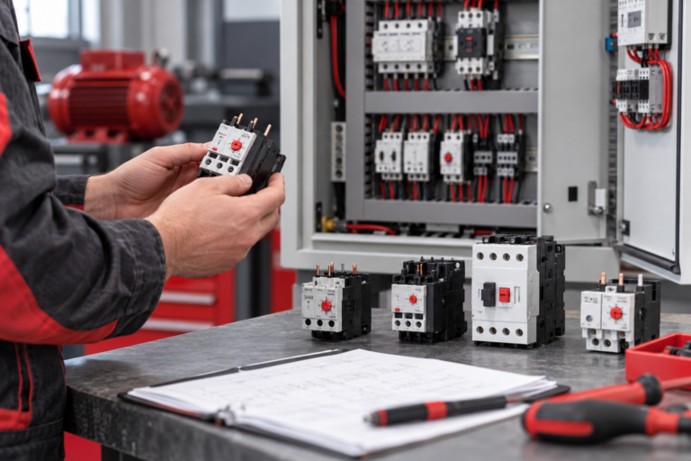
For a replacement, clear photographs of the motor nameplate, contactor label and overload-relay label can remove a surprising amount of ambiguity.
INTEKS supplies industrial electrical protection and control components for panel builders, contractors, maintenance teams and industrial buyers. Providing the actual application data when requesting a component makes it easier to identify the appropriate product option without relying on appearance or one rating alone.
Frequently asked questions
Does an overload relay replace an MCB or MCCB?
No. An overload relay addresses motor overload conditions, while suitable circuit protection is still required for faults such as short circuits. The complete protection arrangement should be selected for the installation.
Should the overload relay always be set exactly to the motor nameplate current?
The motor nameplate current is a key starting point, but the final setting must follow the relay manufacturer's instructions, applicable electrical rules and the actual starter arrangement. Star-delta circuits, for example, can require different settings depending on where the overload relay is installed.
Schneider Electric
+1
Can I use motor kW to choose an overload relay?
Not by itself. Motor voltage, rated current, starting arrangement and the relay's adjustment range also need to be considered.
What should I do if an overload relay keeps tripping?
Do not simply increase its setting. Check actual motor current, mechanical load, phase condition, motor data, starter design and the manufacturer's specified settings. A qualified electrical professional should investigate unexplained repeated trips.
What information is most useful when buying a replacement?
The existing relay part number and range, contactor model, motor nameplate, supply information and starter configuration provide a much stronger basis for replacement selection than physical appearance alone.
Related INTEKS guides
- AC-1 vs AC-3 Contactors: Why the Same Contactor Can Have Different Current Ratings
- Phase Failure and Phase Sequence Relays: What They Actually Do in a Three-Phase System
- Browse all INTEKS technical insights
For project requirements, component identification or a panel enquiry, contact the INTEKS team with the relevant rating, application and existing product details.
For the applicable standard and current edition, consult the official IEC publication search.